Embedded Programming
The assignment for this week is to read the mircocontroller data sheet and program my board in week 6 with many different programming languages and programming different environment.
Tools needed for this week:
1- hello board done in week 6
2- Arduino- software for programming
3- Ebot – program for testing
Reading the Data Sheet:
I never did programming in my life but for fabacademy it a required subject and a good experience. A lot of components are required to understand and use like resistors, capacitors and aTtiny 44 in which most of them I don't recognize since college and some don't understand it at all.
Microcontroller:
I read some information about the components using the web to understand better on what I am doing and the most important components is the Attiny 44 due that it have six pins with different roles.Micro-controller
programming or burning a microcontroller means to transfer the program from a compiler to microcontroller the program of a microcontroller is generally written c or assembling language finally the compiler generate a hex file which contains the machine language instruction understandable by a microcontroller.
How to program a microcontroller
For the programming, we need A programmer is a hardware device with dedicated software which reads the content of the hex file stored on the PC or the laptop and transfers it to the microcontroller to be burned.
Microcontroller is a very small electronic chip designed for embedded applications. It contains one or more CPUs (processor cores) along with programmable input/output peripherals and memory. The memory in a microcontroller divided into 3 types :
1.SRAM is the type of memory where data must be read and written to repeatedly. This is the data will change the different code being uploaded to the AVR microcontroller circuit. By default, this is the most common and used type of memory.
2.Flash memory is the memory that normally stores data that does not change. This is the program memory. It stores the part of the microcontroller program that is fixed and will always stay permanent.
3.Registers are small memory elements in microcontrollers with 8 bits capacity. Registers can be accessed quickly by the ALU (Arithmetic and Logic Unit) of microcontrollers
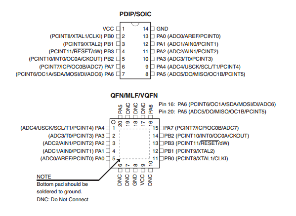
Attiny 44 pins:
1)SCK=Programming clock, generated by the In-System Programmer (Master)
2) MISO=Communication line from target AVR (Slave) to In- System Programmer (Master)
3)GND=Common Ground
4) RST=To enable In-System Programming, the target AVR Reset must be kept active. To simplify this, the In-System Programmer should control the target AVR Reset
5)MOSI=Communication line from In-System Programmer (Master) to target AVR being programmed (Slave )
6) VCC=voltage
Problems:
I faced a lot issues in this week since the my design didn't work in programming and an error showed while testing. Our assumption to this error due to the bit being worn out and were waiting for it to be replaced.
Solution for it is to mill a new hello board and try to solder the components again and increase the route space from .016mm to .022 mm then test it for programming.
My initial design with an error
I increased my route space to 0.022m in eagle and configure my schematic again so that it can reach 100% using the auto router and I increased my of the board.
The schematic for the hello board
The new design
The Board file
Programming:Using Adruino we used the following codes:
// constants won't change. They're used here to
// set pin numbers:
const int buttonPin = 2; // the number of the pushbutton pin
const int ledPin = 13; // the number of the LED pin
// variables will change:
int buttonState = 0; // variable for reading the pushbutton status
void setup() {
// initialize the LED pin as an output:
pinMode(ledPin, OUTPUT);
// initialize the pushbutton pin as an input:
pinMode(buttonPin, INPUT);
}
void loop() {
// read the state of the pushbutton value:
buttonState = digitalRead(buttonPin);
// check if the pushbutton is pressed.
// if it is, the buttonState is HIGH:
if (buttonState == HIGH) {
// turn LED on:
digitalWrite(ledPin, HIGH);
} else {
// turn LED off:
digitalWrite(ledPin, LOW);
}
}
The Result: